Personal Thoughts and Shared Work on the Aquatic Purification Line Process
此页面有 中文 版本
当前正在浏览 English,可一键切换到你的偏好语言 中文。
Personal Thoughts and Shared Completed Runs for the Purified Aquatic Line Process
Author: @CX9881, @void
Summary
Starting from the EV tier, purified water is added to the game's progression, and the required grade of purified water increases as the tier of cut wafers rises. A well-designed automated purified water production line can save a lot of hassle (though given that purified water can be mass-produced in parallel as long as power is supplied, you can just craft the later batches manually with full power input for a while). This article, based on the mods included in the modpack, provides automated production ideas and corresponding workflows for tier 1 through 8 purified water.
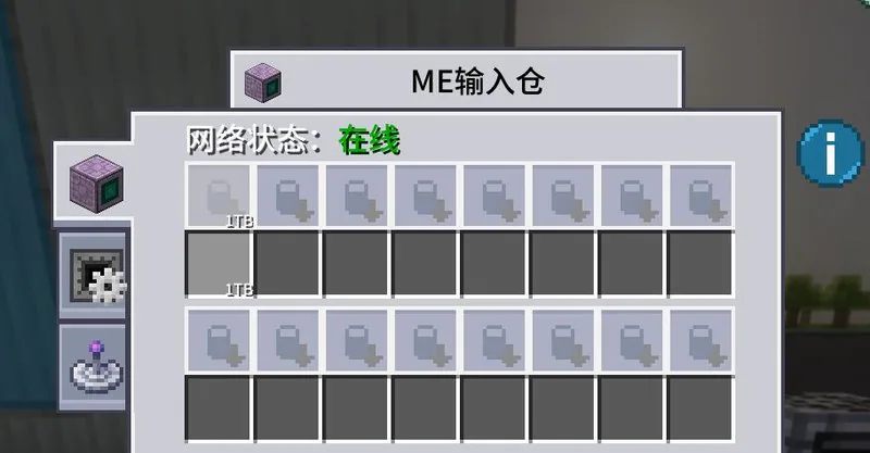
Unless otherwise specified, the switchable ME input chambers mentioned in this articleall use the Machine Control Cover Plate, and the machine cover platesall activate machines when the redstone signal exceeds the set threshold.
This article was written for version 0.5. Level 1-4 Water may be reworked in the future. If you see that the description does not match the in-game content, please do not just copy blindly. You can wait for the author to update it or research it yourself.
Purified Water FAQ
Q:Why isn't my Level 1 Water Plant working?
A:Backwash requires the output bus to discharge waste, and the parallel requirement must be greater than 1000.
Q:Why can't my water purification plant work at the same time?
A:Insufficient power. Taking tier 1 water as an example, processing 1mb of water in parallel consumes 1 EU. Advanced purified water has higher energy consumption. For details, refer to the main tooltip of the water purification plant. When the parallel processing count is too high, one tier of purified water will monopolize all power, causing other water treatment plants to shut down.
Q: Adjusting the parallel settings, why doesn't the water plant work anymore?
A:After adjusting the parallel mode, if the main plant does not refresh automatically, try turning the purified water main plant on and off.
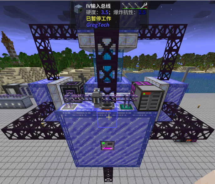
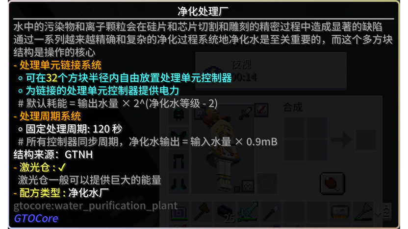
Central Control Purification Plant
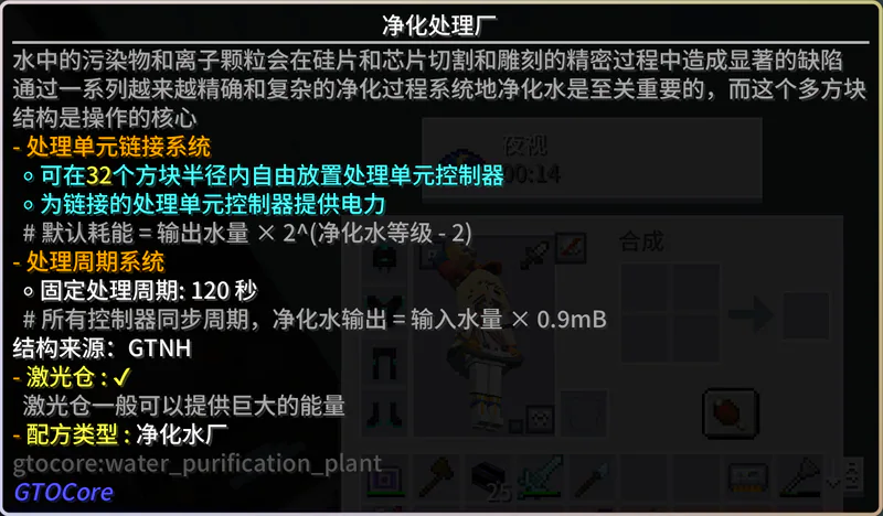
Central multi-block structure for water purification that controls nearby water treatment plants of all tiers and supplies power. The main blocks of water treatment plants of all tiers will automatically connect as long as they are within the spherical range displayed in the Water Purification Plant's GUI. This 120-second fixed processing cycle cannot be accelerated by methods such as overclocking or power boosting, but can be accelerated by time distortion (not recommended).
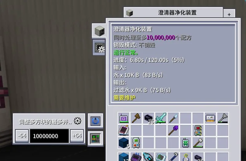
T1 Clarifier Purification Unit
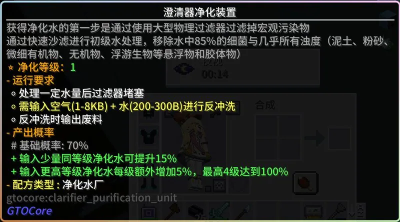
This is the easiest water purification setup to automate; just follow the provided instructions. The input hopper supplies regular water and advanced purified water. If you don’t have these items yet, skip adding them for now and remember to top them up later once you progress further.
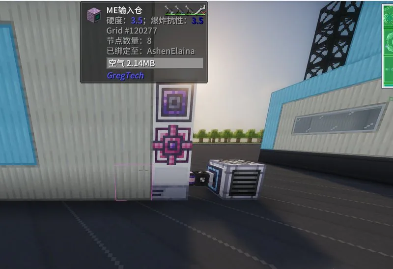
According to the tooltip, we also need to add air for backwashing. Given that the regular input bin is far from sufficient during the EV phase, an additional ME input bin is added here to input air.
Then use this ME input bus to create a separate network, connect an ME chest (fluid storage component) to the outside of the network, and place an air collection chamber to feed air into this ME network.
After placing it, remember to access the main block's GUI and adjust the parallel count based on the supplied electric power, laterAfter each tier of purified water is produced, you must manually adjust the parallel count, with 1 parallel corresponding to processing 1 mb of input water
T2 Ozone Purification Device
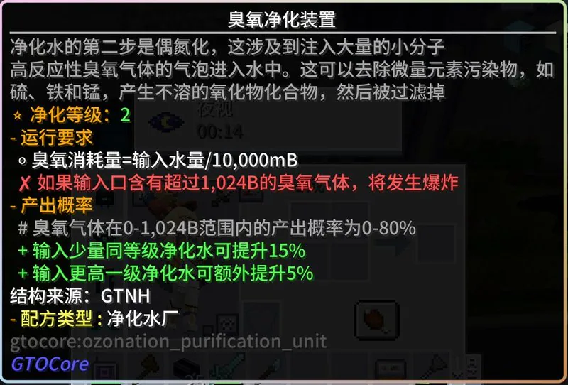
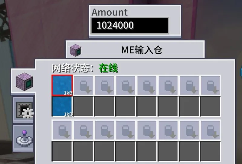
According to the tooltip, the best way is to always keep 1024B of ozone in the input bus. The simplest method is still to use ME input bus markers. Prepare two ME input buses: the first one is connected to the main network, used to input the previous-stage purified water and the advanced purified water to improve the success rate.
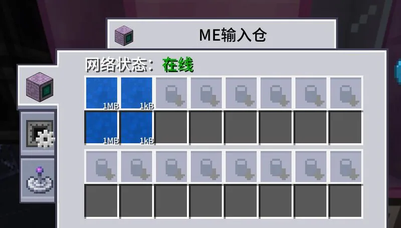
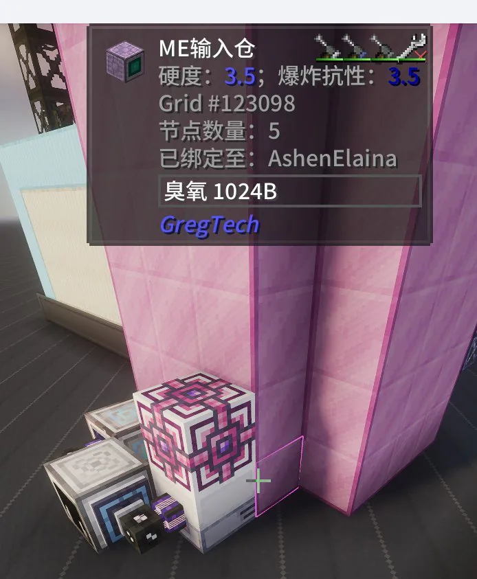
Second ME input chamber: mark 1024B dedicated ozone, do not connect to the main network. Run on its own separate network just like the T1 water and air input system, then connect an external arc generator to produce ozone and feed it into the network.
T3 Flocculation Purification Unit
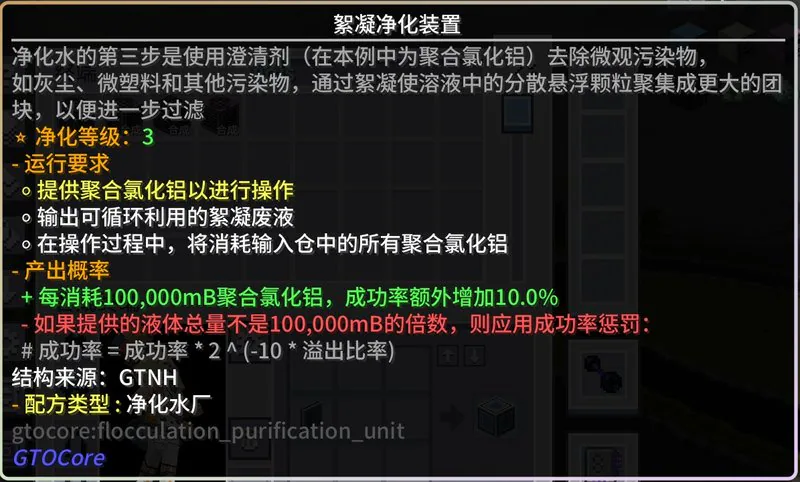
The key to T3 water automation is dosing exactly 1000B of polyaluminum chloride in a single processing cycle. There are roughly two approaches here: timing control and state control, but the core is controlling the switch of the me input bin to regulate the aluminum chloride input.
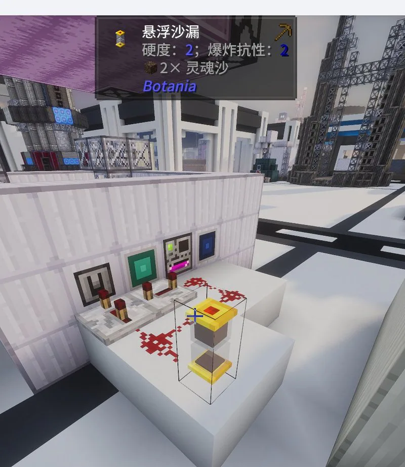
The timing control principle is to input once every 120 seconds. Please refer to the figure below. Since I didn't create this, I won't go into details.
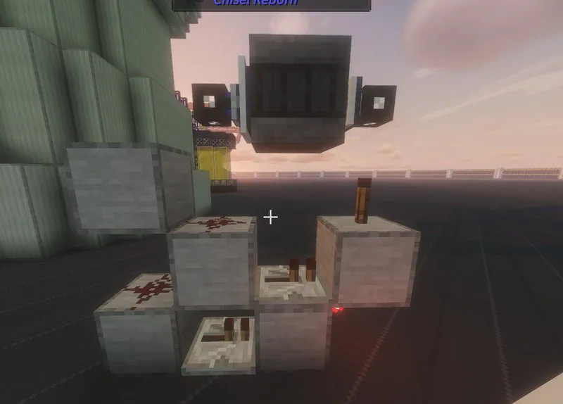
The state control principle is to output a signal after the machine completes its cycle to control the input of polyaluminium chloride. In this setup, after the recipe is finished, the ME Output Bus (not connected to the main network) outputs via two storage buses. The upper storage bus is labeled flocculation water, while the lower storage bus facing the tungsten steel barrel is labeled flocculation waste liquid. A fluid calibrator is installed on the left side of the tungsten steel barrel to output through the left-side ME oversized interface (12500mb/t). A fluid detector cover plate (set to default) is placed below it, which controls the lower ME Input Bus to activate for a set duration when the recipe completes. The ME Input Bus is labeled with 1000B polyaluminium chloride. During the first run, manually enable the input of 1000B polyaluminium chloride, then disable it, after which the system will run automatically.
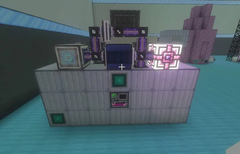
Remember to add an extra distillation unit to recover the flocculation waste liquid.
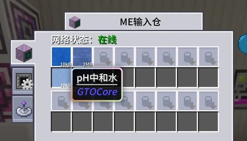
T4 pH Neutralization Purification Device
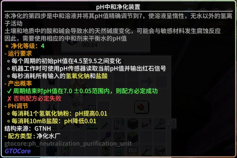
T4 water can be fitted with two pH detectors. When readings exceed either the upper or lower bounds of the detection range, send a redstone signal to adjust the corresponding ME input chest/input bus switch accordingly (add base if too acidic, add acid if too alkaline).
The left pH sensor ranges from 7.05 to 14, and the right one ranges from 0 to 6.95. The left side is the ME input chest, marked with 40ml hydrochloric acid, and the right side is the ME input bus, marked with 4 units of sodium hydroxide powder. Use Redstone P2P for connection.All ME chambers are fitted with Machine Control Cover Plates.
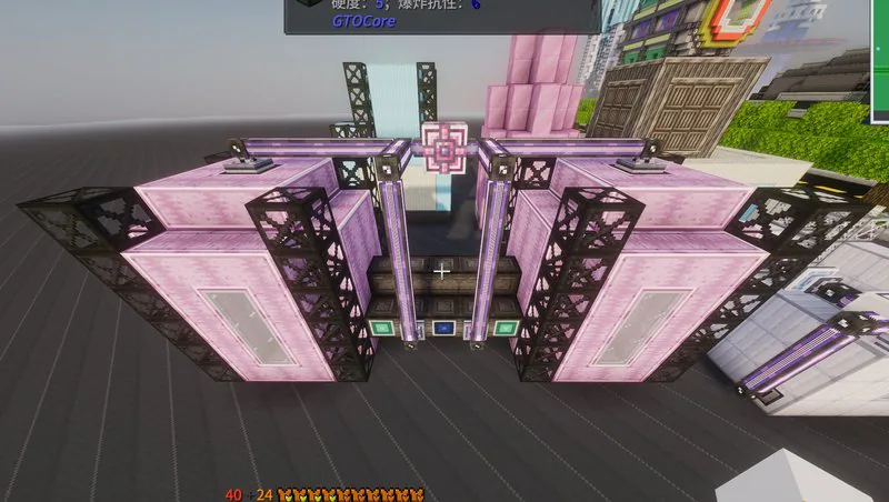
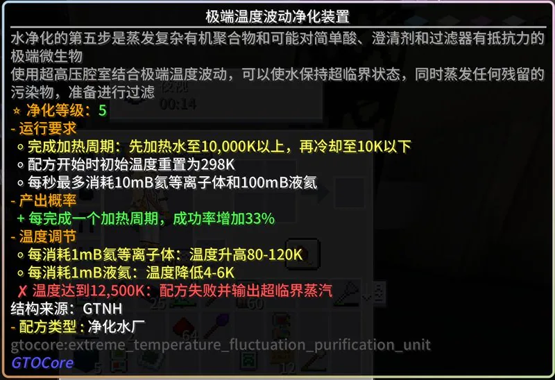
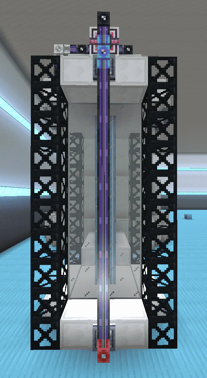
T5 Extreme Temperature Fluctuation Purification Device
The automated task requires completing three temperature cycles within 120 seconds, similar to the previous T4 water. The approach is also roughly the same as that of T4 water.
The core redstone circuit is roughly as follows (actually, there's only one latch).
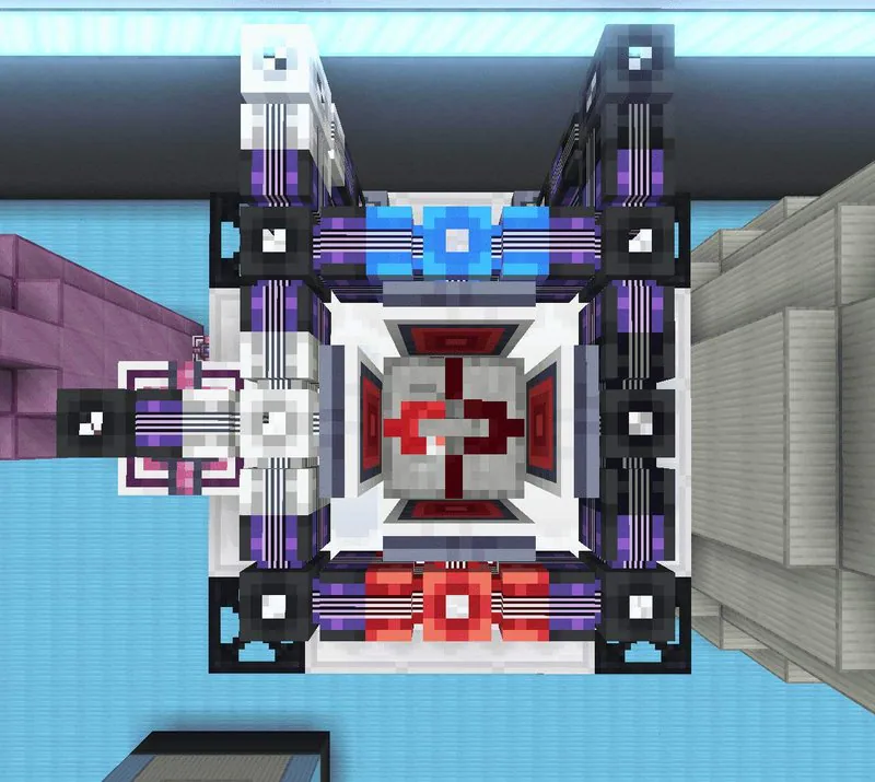
Same-colored P2P redstone belongs to one channel.
Red indicates the overheat sensor circuit, with personal settings ranging from 10000 to 12500.
Blue is the supercooling sensor wiring, personal setting is 0-10.
White is the helium plasma control line, the ME input bay is marked with 20ml helium plasma.
Black is the liquid helium control line, the ME input bay is marked with 400ml liquid helium.
It can be done with a single sensor, but it's a bit more troublesome.
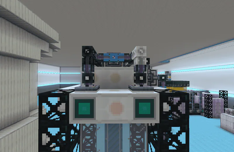
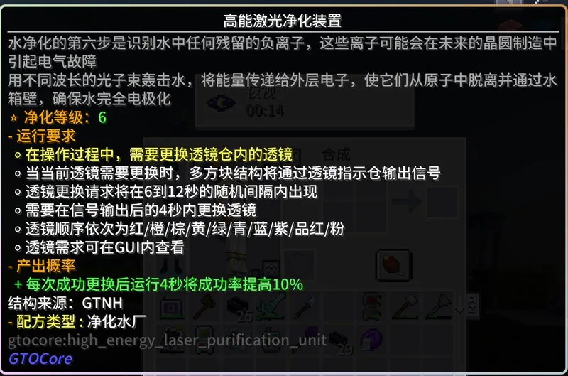
T6 High-Energy Laser Purification Device
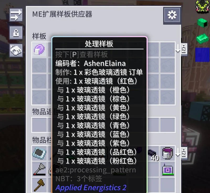
For periodic cycle lenses, there are quite a number of schemes, including super chest queues and ender conduits combined with redstone. However, I personally find the pure AE order scheme by Xieying from the group to be the most convenient. The control structure of the AE order scheme is shown below.

Mark orders on the output bus beneath the wooden barrel (with a synthesis card installed). The hypercube is bound to the lens chamber, and the right-side input bus of the hypercube (equipped with a redstone card) is responsible for extracting lenses. Place the synthesis template in the template supplier above the hypercube. The templates are as follows (note the lens order).
After placing the machine, you should manually align the axis with the machine's lens sequence. The general procedure is to break the Redstone, wait until the GUI prompts that the lens matches the one in the compartment, then connect the Redstone.
T7 Residual Contaminant Degassing Purification Unit
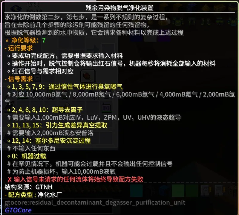
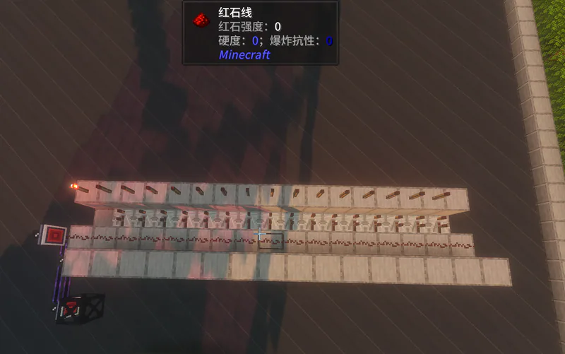
It can be decoded, but using direct redstone signal strength selection + enumeration is less mentally taxing. It just takes up more space, though. The general approach is to first determine the signal strength, then input the corresponding fluid into the machine via the matching signal line. The complete control structure is as follows.
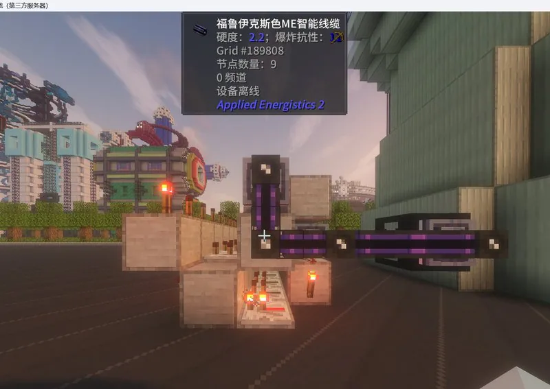
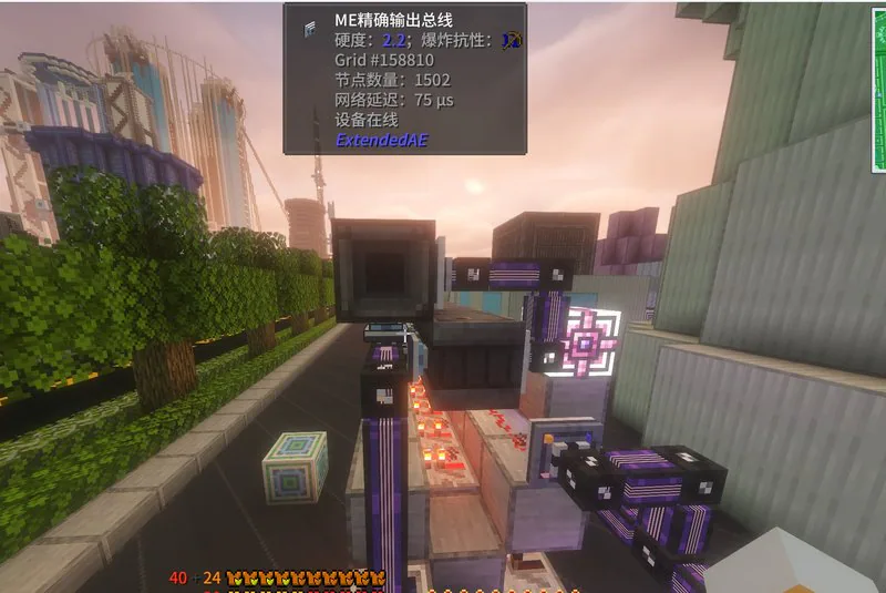
It is divided into two parts: Redstone signal strength selection and fluid output. The single modules for 1 to 15 are as follows. The left side of the steel bucket is the storage bus, and the right side is the precision output bus. The emitted Redstone strength signal only activates the single modules in this column after selection. When the precision output bus of the upper-right Redstone torch (which contains a crafting card, Redstone card, and is set to pulse activation) receives a rising edge signal, it performs one output to the steel bucket. The row of storage buses on the left forms a separate network, connecting to the machine's ME inventory input slot to achieve automatic input.
Roughly, this is how the single Signal Strength 0 module is placed. The image below shows the control section containing only the signal strength selector. The quartz frame area is where the degassing signal is output, which is transmitted at two locations via redstone P2P.
After the setup is complete, mark the corresponding amount of liquid on the precision output bus matching the signal strength. Since the precision output bus can only output 8B at a time, an additional output needs to be set up for gaseous helium and liquid helium as shown in Figure 2, with 8B going to steel drums and 2B going to super tanks.
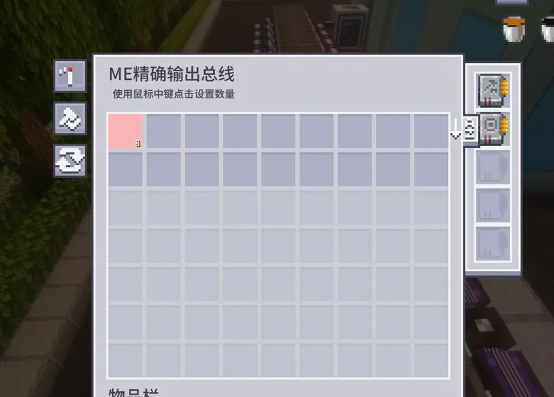
Given that the exact output bus for EAE cannot adjust its quantity (unclear whether this is a bug from EAE or GTO), here’s a workaround idea. Use the ME oversized interface to mark the corresponding fluid, adjust the quantity, then press A to save it to the left favorites folder, then drag the mark on the exact output bus page.
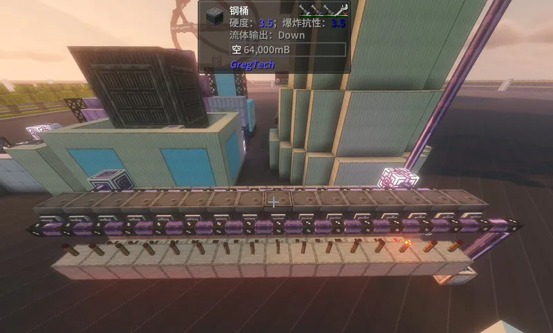
T8 Absolute Baryon Perfect Purification Device
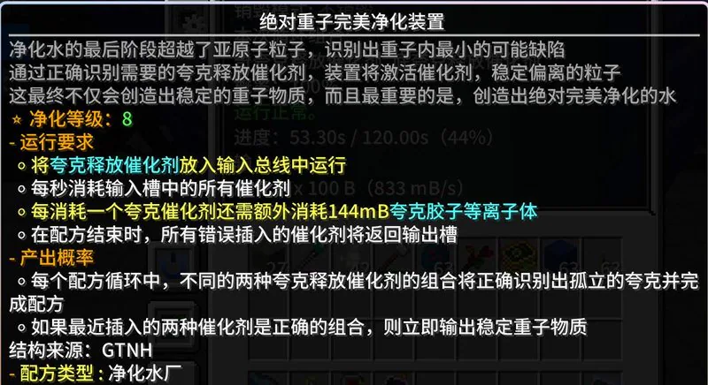
For the T8 water mechanism that has no signal indication, we can only solve it through traversal. Below is one of the simplest solutions for the single-order T8 water.
First, you need to determine the initial order to prevent writing confusion (for example, assign Up, Down, Top, Bottom, Strange, Charm to 1, 2, 3, 4, 5, 6 respectively), then divide into 6 groups A, B, C, D, E, F. Each group contains six catalysts, which are named using their group number (for example, for group A, use the stamping die naming convention to name all six catalysts as A). Then determine the arrangement order:
Group A: 123456
Group B: 246135
Group C: 146325
Group D: 523641
Group E: 531642
Group F: 654321
Since both the end of Group C and the start of Group D use Catalyst No. 5, we omit one Catalyst No. 5. Finally, arrange them in the order ABCDEF, then add 35*0.144=5.04b of quark-gluon plasma and a certain amount of degassed water to obtain the following template.
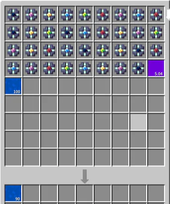
12345624613514623523641531642654321This sequence contains all 30 types of adjacent situations.
Finally, use subnets for deployment.(Please use iv input bus)